Wiring Instruction
- Noodle Team

- Jan 8, 2020
- 4 min read
Updated: May 9, 2020
See the bill of materials document for purchasing information for all parts.
Parts needed for this section of the project:


Soldering the Drivers
If you have not soldered before, go through the following guide (https://www.makerspaces.com/how-to-solder/) to learn the process. It is important that proper safety precautions be taken, especially if you are unfamiliar with soldering. Please review this document and remember that the soldering iron is HOT, as is anything the iron comes into contact with. DO NOT touch the board anywhere near where you are soldering or have soldered without giving it time to cool.
Next, take your strip of male header pins and break off 8 individual pins, 8 pairs of pins, and 4 sets of 3 pins. They should look like the following, image taken from Sparkfun item listing.

For each driver, place these pins into the RST, ENABLE, MS2, GND, M+, MS1, GND, STEP, and DIR holes as shown in the image below.

Carefully flip the drivers over, so that the board is standing on the pins. Now use the soldering iron to solder the pins to the holes. The pins should be secure (they shouldn't move). Check that no metal has crossed between the metal pads or pins. If they have, use the soldering iron to carefully remove the excess solder.
Don’t worry if you make a mistake. If a pin comes loose, all you have to do is add more solder to attach it better. If a hole becomes blocked, use pliers to hold the pin and heat the hole clogged with solder. Once hot enough, you can use the pliers to press the pin through the melted solder and proceed as before.
Next, solder in the wires coming from the stepper motor. From left to right, the colors should be red, green, yellow, blue. The image below also demonstrates this.
If the wires begin to fray from attempts to make the connection, there are a few things you can try. First, use pliers to try straightening then twisting together the copper threads. If this doesn’t work, or too many of them have broken, you can use wire cutters and wire strippers to create a fresh end. To do this, cut off all the current ends past the plastic then clear about an inch of the insulation with the strippers.

Once completed, the driver board should look like the following image. Repeat this for all four drivers and motors. Check the wire connections for stray copper. DO NOT use the driver if it appears that there is copper from one wire appearing to cross with any other metal on other wires or on the board. Use wire cutters to trim these off.

Wiring the Drivers, Power, and Arduino
When wiring, we would suggest that you leave as many wires as possible connected in the strips they come in. For example, each set of nine pins on one driver can be wired using a strip of nine wires. This will both make it easier to organize your wires and easier to debug if an error occurs.
Prepare the 12V supply by connecting two wires to the screw terminals provided. Use a screwdriver to loosen the ports, insert the wire (with metal exposed), and screw the terminal back down until lightly tugging on the wire does not result in the wire coming out. Make sure and use a red wire for the + port and a blue wire for the - port if you can as these are standard colors.

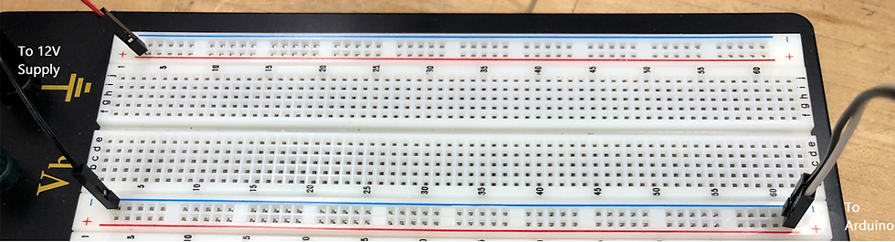
Before the next step, we will give a quick explanation of breadboard connections. Each long strip of holes with a line of color next to them are connected in the direction of the colored strip. These are called power buses, and they make it easier to wire power to parts. On the rest of the board, each row of 5 pins perpendicular to the power buses is connected. They are numbered, shown along the sides. See the image below for a visual explanation of these connections. The blue and red lines are the buses and the green lines indicate a few sample rows.

Connect the power wires to the breadboard as below. Do NOT plug anything into the wall yet. Connect the 12V (the "+" on the power supply) wire to one of the red "+" lines on the breadboard. Connect the 5V pin from the Arduino board to the other red "+" line on the breadboard using a wire. This pin name can be found written on the board. DO NOT connect these two red lines together.
Now take the "-" line from the power supply and connect it to one of the blue "-" lines on the breadboard. Connect one of the pins labelled GND from the Arduino, also written on the board like 5V label was, and connect it to the same blue "-" line on the breadboard. These have to be connected as these are what are called the ground lines, or GND for short. The ground line is used to drain away electricity that comes in from the power. If they aren't connected, the power from the Arduino and from the wall cannot work together in the robot.
You are now ready to put in the wires. If your board does not have well labelled pins, refer to the following diagram from store.arduino.cc/usa/arduino-uno-rev3. Note that any pin referenced by just a number is a digital pin, not an analog pin. This means pin 4 is D4 not A4.


First, connect the analog stick leads to the arduino pins as described both in the table and picture below. Also connect the GND pin to the GND line on the breadboard as shown.


Now take each motor driver and connect it to the breadboard power as shown on the right.


Next, take the motor drivers and connect them to the Arduino based on which motor they are connected to using the table on the right.
The final result may look like the following, but don’t worry if the wires appear more cluttered. You can use zip ties to cluster them and keep it more organized.
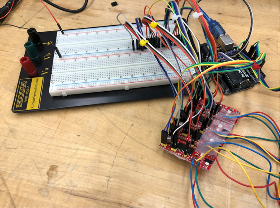
Finally, plug the Arduino and motor supply in. Proceed to program the arduino using the programming instructions. Below is a complete wiring diagram.


Comments